hello every body,
Me back again with some information , some quaries for you .
So basically what is PID loop?
It is Proportional, integral, derivative loop for any control situation in any industary ,device ,or any machine that need a precise working and caliberation to perform a very specific and important work in which a small error can lead to a loss and damage and irregularity in the desired output.
Just like if we take a example of a PID loop application in robotic arm which is used in PICK AND PLACE department in an industry.
and it work in autonomous mode.it has to pick a boul filled with hot chemical at 0degree(lets assume its initial position).and has to pour 50 ml of it in another boul placed at 60 degree and at 15 cm height.
so a PID lop must have some input from different sensors ,on which it will work, a microprocessor or CPU which will manipulate the inputs and will generate the desired output.
sensor 1= A digital compas which will give orientation of the arm in XY plane ,
sensor 2= a accelerometer and gyroscope which will give output along the height of the robotic arm .
a touch sensitive device which will sense the height of liquid in the boul .
now we had some specific PID loop terms that are need to be specify here.
Sensing the orientation along the XY plane,height and level of water is analogous to taking a measurement of the process value or process variable (PV).
The desired rotaion angle along XY plane ,along vertical plane and height of chemical in boul is called the setpoint (SP).
The input to the process is called the manipulated variable (MV).
The difference between the PV and the setpoint is the error (e), that quantifies whether the proper action has been taken place or not.
so here is the application of all the specific terms.now is the starting of the PID loop appliaction takes place.
In the very next blog i will discuss the theory and thinking behind the process which take place in controlling the robotic arm .
Sunday, December 5, 2010
Tuesday, November 16, 2010
taken from WIKIPIDEA,but yes is really helpfull for a safe landing of medium scale amateur vehicles
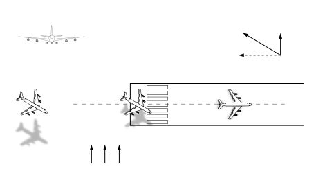
A crosswind landing is a landing manoeuvre in which a significant component of the prevailing wind is perpendicular to the runway centerline.

 B-52 performing a crab landing having nose pointed toward incoming wind, but undercarriage aligned along the runwayIn situations where a crosswind is present, the aircraft will adopt a yaw orientation with respect to the runway and will drift laterally as it approaches the runway. These pose significant safety issues when safe operation of the undercarriage requires the body and the velocity of the aircraft to be aligned with the runway at touch down. The landing gear on the B-52 included an unusual feature to counteract the problem: all landing gear bogies could be steered, allowing the aircraft to land with the wheels facing the direction of travel even if the nose was not pointed in the same direction.
To meet these conflicting requirements, three standard procedures are used for executing a safe landing in a cross wind situation. These landings are called the Crab, De-Crab and Sideslip techniques.
If the crosswind landing is not executed safely, the aircraft may experience wingstrike, where a wing hits the runway.
 The objective of this technique is to maintain wings level and the aircraft position near the runway centerline during approach. The nose points into the wind so that the aircraft approaches the runway slightly skewed with respect to the runway centerline (crabbing). This gives the impression of approaching the runway flying sideways, which can be disorienting for the pilot. Position is maintained by balancing the crosswind component, or more accurately the drag force arising from it, with engine thrust. Wings are maintained level throughout the approach. Just before the flare, opposite rudder (downwind rudder) is applied to eliminate the crab, with a simultaneous application of opposite aileron to maintain a wings-level attitude, so that at touch down, the body, velocity vector, and bank angle are all aligned with the runway, and the aircraft is positioned near the center.
 The airplane can land using crab only (zero side slip) up to the landing crosswind guideline speeds.
On dry runways, upon touchdown the airplane tracks towards the upwind edge of the runway while de-crabbing to align with the runway. Immediate upwind aileron is needed to ensure the wings remain level while rudder is needed to track center line. The greater the amount of crab at touchdown, the larger the lateral deviation from the point of touchdown. For this reason, touchdown in a crab only condition is not recommended when landing on a dry runway.
On very slippery runways, landing the airplane using crab only reduces drift towards the downwind side of a touchdown, and may reduce pilot workload since the airplane does not have to be de-crabbed before touchdown. However, proper rudder and upwind aileron must be applied after touchdown to ensure directional control is maintained.
 This sideslip crosswind technique is to maintain the aircraft's heading aligned with the runway centerline. The initial phase of the approach is flown using the Crab technique to correct for drift. The aircraft heading is adjusted using rudder and ailerons to align with the runway. This places the aircraft at a constant sideslip angle, which its natural stability will tend to correct. Sufficient rudder and aileron must be applied continuously to maintain the sideslip at this value. The dihedral action of the wings has a tendency to cause the aircraft to roll, so aileron must be applied to check the bank angle.
With a slight residual bank angle, a touchdown is typically accomplished with the upwind main wheels touching down just before the downwind wheels. Excessive control must be avoided because over-banking could cause the engine nacelle or outboard wing flap to contact the runway/ground.
In strong crosswind conditions, it is sometimes necessary to combine the crab technique with the sideslip technique.
Contents[hide] |
[edit] Significance
Aircraft in flight are subject to the direction of the winds in which the aircraft is operating. For example, an aircraft in flight that is pointed directly north along its longitudinal axis will, generally, fly in the that northerly direction. However, if there is a west wind in the air in which the aircraft is flying, then the actual trajectory of the aircraft will be slightly to the east of north. If the aircraft was landing on a northbound runway, it would need to compensate for this easterly component of velocity caused by the west crosswind.
To meet these conflicting requirements, three standard procedures are used for executing a safe landing in a cross wind situation. These landings are called the Crab, De-Crab and Sideslip techniques.
If the crosswind landing is not executed safely, the aircraft may experience wingstrike, where a wing hits the runway.
[edit] Techniques
The following guidelines are advised by Boeing for a crosswind landing. These guidelines assume steady wind (no gusting). These winds are measured at 10 m (33 feet) tower height for a runway 45 m (148 feet) in width. Basically, there are 3 landing techniques which may be used to correct for cross winds: De-Crab, Crab, and Sideslip.[edit] De-Crab

crosswind
crosswind
component
component
thrust vector
runway
component
component
touchdown
De-crab
[edit] Crab

crosswind
crosswind
component
component
thrust vector
runway
component
component
touchdown
Crab
On dry runways, upon touchdown the airplane tracks towards the upwind edge of the runway while de-crabbing to align with the runway. Immediate upwind aileron is needed to ensure the wings remain level while rudder is needed to track center line. The greater the amount of crab at touchdown, the larger the lateral deviation from the point of touchdown. For this reason, touchdown in a crab only condition is not recommended when landing on a dry runway.
On very slippery runways, landing the airplane using crab only reduces drift towards the downwind side of a touchdown, and may reduce pilot workload since the airplane does not have to be de-crabbed before touchdown. However, proper rudder and upwind aileron must be applied after touchdown to ensure directional control is maintained.
[edit] Sideslip

crosswind
crosswind
component
component
lift vector
runway
component
component
touchdown
Sideslip
With a slight residual bank angle, a touchdown is typically accomplished with the upwind main wheels touching down just before the downwind wheels. Excessive control must be avoided because over-banking could cause the engine nacelle or outboard wing flap to contact the runway/ground.
In strong crosswind conditions, it is sometimes necessary to combine the crab technique with the sideslip technique.
Monday, November 15, 2010
FINDING OUT THE EFFECT OF WIND VECTOR ON UAV:- How much it effect the movement of uav if neglected on small scale
Introduction
Drag is the resistance to motion of an aircraft flying through the air generated by a combination of pressure and friction. This resistance is overcome by the engines.Modern civil aircraft are designed to minimise drag in order to reduce the environmental and economic costs of flying. By reducing drag, the amount of power needed from the engines is lessened and as a result the amount of fuel required is also reduced. Less fuel means a lower environmental impact and lower costs for the airline.
Aircraft manufacturers can reduce drag in a number of ways – be it with a subtle change in geometry like adding a winglet or a more substantial change of configuration like changing the shape of the wings or repositioning the engines.
The Role of Wind Tunnels
Wind tunnels play a crucial role in the design of modern, greener aircraft. Improvements to aircraft designs are initially made using computer models. But even the most powerful of today’s computers cannot generate a perfect simulation of the air flowing around a complete aircraft. So when a design is sufficiently advanced, it is tested in a wind tunnel to check that the computer predictions are correct and that the designers have correctly understood what is happening to the air as it flows around the aircraft model.MY THEORY:-
In mine project when i use to talk about the wind vector i think its a useless thing for mine project.As its a fact that it play a important role in determining the aerodynamical model of the plane through which the consumption of the fuel can be reduced to much extent.
But as far as i am concern regarding mine project,when we are using the pre-prepared aeromodel for our project it is useless to find out the drag force or wind vector that has been applied on the aircraft.Infact finding out the wind vector is also important in determining the inclination of the aeromodel with respect to the earth inertial frame of reference if the wind vector is caliberated with gps output.
But when we have sensors like ACCELEROMETER and GYROSCOPE to determining the inclination of aeromodel with respect to the earth inertial frame than i think we need not to bother much about determining wind vector( Thats an easy approach) using complicated functions
well its what all ii think.well in the next post i had got something to determine the inclination of any inertial frame with respect to earth inertial frame with and without using the KALMAAN filter.
Sunday, November 7, 2010
SOME COURAGEOUS LINES
"Few men are willing to brave the disapproval of their fellows, the censure
of their colleagues, the wrath of their society. Moral courage is a rarer
commodity than bravery in battle or great intelligence. Yet it is the one
essential, vital quality for those who seek to change a world which yields
most painfully to change."
-- Robert F. Kennedy 1966 Speech, US Democratic Politician
Here's to the crazy ones, the misfits, the rebels, the troublemakers, the
round pegs in the square holes... the ones who see things differently --
they're not fond of rules... You can quote them, disagree with them, glorify
or vilify them, but the only thing you can't do is ignore them because they
change things... they push the human race forward, and while some may see
them as the crazy ones, we see genius, because the ones who are crazy enough
to think that they can change the world, are the ones who do.
-- Steve Jobs, US computer engineer & industrialist (1955 - )*
**
**
Saturday, November 6, 2010
SImplest inexpensive,feasible, and energy harvesting mechanical project
work going on...............wait for some more time
Wednesday, November 3, 2010
AMATEUR UAV "SURYAAN"
ARMATURE UAV – A APPROACH FOR DEDICATED SENSOR APPLICATION.
BY:-Shailendra singh, CEST, Lucknow
Under the guidance of Dr Priya Ranjan, Ex Assistant Prof., IITK
AIM:-To construct an ARMATURE UAV (unmanned aerial vehicle), for surveillance at small level and have an auto-pilot flight for the desired mission various other works.
PROJECT SPECIFICATION:-
An Aero-model with a auto-pilot kit that will be made by me. Presently working on its PCB layout. Kit will include:-
1) At-mega128
2) Gps
3) Gyroscope
4) Xyz horizon sensor or accelerometer
5) pitot tube
6) Camera and zigbee-pro.
7) Compass (for direction).
8) A software to track wave point on our system (integrating Google earth with gps)
THEORY:-
Kit will be programmed with win-avr programmer using embedded C programming language. Project will be carried out in 4 steps.
1) Developing the electronics using eagle-pro pcb layout development software.
2) Developing the programming needed for auto-pilot mode.
3) Testing the programming during flight only.
4) Developing the programming for auto Take off and landing.
FOR AUTO-PILOT(DESIGN)
1)First of all the microprocessor at-mega- 128 will be programmed for the pre-installed gps coordinates taken with the help of Google earth for the particular mission.
2) When the aero-model will fly and present time coordinates of the gps satellite instrument will meet with pre-installed coordinates, particular line of code will be executed will give direction to the aero-model to the next coordinate.
3) For the particular angle of bank and drift angle, the aero-model will reach the second coordinate and the stability of the flight will be ensured with the help of gyroscope and xyz horizon sensor combination or gyroscope or accelerometer combination.
4) Aero-model will send the video taken during the flight will the help of Zig-bee pro wireless module. The camera installed in the aero-model will move 2-dimensionally.
FINDINGS:-
During working on the theory of this project it was found that the basis of any auto-pilot system is GPS.It is the GPS which give the exact location of the position of the system with a very little bit of error unlike DEAD REKNOCKING SYSTEM.
Also the use of Accelerometer along with Gyroscope for the stability of the airframe is found.
AIM BHIND PROJECT:-
Our aim behind this project is to enhance our knowledge in ROBOTICS AND AEROMODELLING and to learn the technical skills and how to implement them in our practical life beside lab practicals.
Our aim is to built a fully ARMY purpose PRE-PROGRAMMED/MANUALLY controlled SPY aircraft that also has the ability to strike in the enemy territory
Presently India is spending about 1180 crore rupees in importing UAV’s from Israel and America, but
India doesn’t have the complete technology or may be have like LAKSHYA (developed by HAL). But we are introducing very new not very precise but basic concept with less investment.
RESEARCH LIMITATIONS:-
1)It will be not be made on industrial scale and will be a research cum project cum hobby.
2)It is not powered by a jet or a reciprocating engine.
3)Low speed.
4)Range of operation is less.
5)Cannot carry more weight.
6)Camera resolution and accuracy is less.
Many new applications can be added to it in the futre to make it more advance and accurate
PRACTICAL IMPLIMENTATION:-
Watching the news of KARGIL war in T.V. make me to think that when we have one of the best institutes and brains with us than why we are using man power in wars. At that time a point strikes in my mind that why not we make a small aero-model that too have the capability of spy as well as striker in it.
Infact India has got UAV’s but we are just implementing our technology at very basic and small level.
A movie named as “EAGLE EYE” is also my source of inspiration. This movie shows the basic use of UAV as a spy and striker.
So this model can be used in the following cases if integrated on a little bit large scale using bigger airframe and more efficient reciprocating engine to increase its payload:-
1) Remote sensing
2) Transport
3) Scientific research
4) Armed attacks
5) Search and rescue
2) Transport
3) Scientific research
4) Armed attacks
5) Search and rescue
6)Aerobatics using networking between two or more UAVS
Originality/value:-
Project has been approved by one of the Assistant professor of IIT Dr. Priya Ranjan
And my college faculty member Mr.Avinash Pal .I has also got approval from mine college MD Mr. Abhishek Pal to put it in reality. And I am presently working to prepare the general PID loops equations. Have made he general PCB layout of the Kit which we are going to make on our own.
NEW DIGITAL NOTICE BOARD
GPRS ENABLED LED BULLITIN BOARD
AIM:- To make a LED Bulletin Board enabled with GPRS system and Microcontroller such that anyone having the no of that GPRS system can display any information from anywhere in India through his/her mobile phone.
PROJECT SPECIFICATIONS:-
Project is broadly divided into three parts.
i) LED display.:- A LED display is just a array of leds connected together and for the larger array i.e.120*14 we had to use 8 bit shit register with output latches(3 states) i.e. M54HC595 or M74HC595
ii)Microcontroller unit for controlling the text to be displayed on the LED display(Atmega series microcontroller):- The ATmega8 is a low-power CMOS 8-bit microcontroller based on the AVR RISC architecture.
By executing powerful instructions in a single clock cycle, the ATmega8 achieves throughputs approaching 1 MIPS per MHz, allowing the system designer to optimize power consumption versus processing speed.
iii)GPRS Tx(Mobile phone) And Rx(GPRS modem.):- rhydoLABZ's GSM/GPRS Modem-RS232 is built with Tri-band GSM/GPRS engine, works on frequencies EGSM 900 MHz, DCS 1800 MHz and PCS 1900 MHz The Modem is coming with RS232 interface, which allows you connect PC as well as microcontroller. The baud rate is configurable from 9600-115200 through AT command. The GSM/GPRS Modem is having internal TCP/IP stack to enable you to connect with internet via GPRS. It is suitable for SMS, Voice as well as DATA transfer application in M2M interface.
The High quality aluminium enclosure enables you to use in rugged environmental conditions. The internal Switching Power supply allows you to connect wide range unregulated power supply. Using thi
modem, we can make audio calls, SMS, Read SMS and attend the incoming calls ect through simple AT command.
THEORY:-
The basic theory behind this project is that a GSM/GPRS Modem is device which is just like a mobile phone but is handled via a computer or a microcontroller unit. In this project a message received by the GSM/GPRS device will be given as a Input to the Rx And Tx port or USART port of the atmega series microcontroller most prefebly atmega8 and after that that digital data will be displayed on the LED array with the help of shift register. Programming for the display will be done with the help of embedded C and the compiler that would be used will be CVAvr.
PROJECT DURATION:-
The project will take approximately less than 2 month to be fully completed.
TOTAL BUDJET:-
The total budget of the will be approx 8,000.
PROJECT IMPLIMENTATIONS:-
i) It can act as a bulletin board displaying the necessary information send by any of the Faculty from any where.
ii) It will improve the technical status of the college that we are using digital notice board.
iii) If a speaker is attached to it a call can be made to it announcing any information.
Sunday, October 3, 2010
android phones
Hi every body going through this post,myself shailendra sing (A frog from UPTU well) now going to new horizons,working under Dr.Priya ranjan on Anderoid cell phones application development.Hope so that we will justify the meaning of a engineer as stated by Dr.Priya Ranjan "a true engineer must not be a USER but a DEVELOPER"
Subscribe to:
Posts (Atom)